Welcome to yEd Q&A!
Here you can ask questions and receive answers from other members of the community and yEd developers. And you can tell us your most wanted feature requests.

Categories

How to control manual edge routing

0 votes

I was trying to make a organization chart as follows:

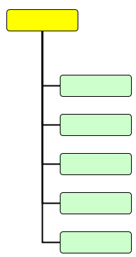
But the Port Constraints would not work as expected (link).

I wanted the following transformation:

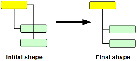
So I tried to select the "elbow" in the edge and move it to the opposite corner.
I expected the bend to snap there, and give me the desired "L" shaped edge.

But yEd creates many more bends and turns the edge into a noodle.

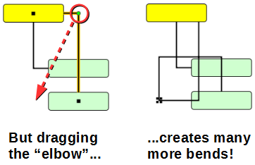
In addition, the "start" point of the edge leaves the center of the yellow node; which is yet another botheration.

I had to select all the undesirable bends and delete them one by one.

Even then the desired shape would not come.

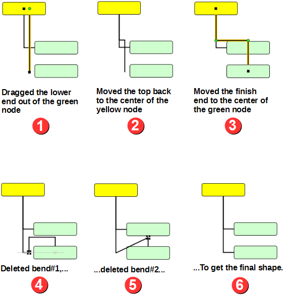
Finally, through trial and error, I found that the easiest way was to begin by dragging the "finish" end of edge outside the green node, and leaving it on the left side of the node.

This method works, but is not easy!

Even then I had to delete and move multiple bends, as shown below.

But this method is simply too tedious.

Is there a better way to achieve the same result? For example, if I press CTRL or some other key while dragging the bend, yEd should not create more bends.

Note that I want the vertical stem of all the edges to be perfectly aligned in a single line; not run parallel in a "bus" formation.

in Help by (1.5k points)

1 Answer

0 votes

Well, yes, there is a better  way to achieve the same result!

First off, do not create the undesired edge path in "Initial Shape" in the first place. Either follow the instructions in my answer to The port constraints do not work for manually created edges (using SHIFT to switch the order of horizontal and vertical segments during the creation of orthogonal edges) or do not use "Orthogonal Edges" mode but rather "Snap Lines" (which make it very easy to create orthogonal edges as well but offer much more control over the actual edge path) or use e.g. "Layout" -> "Edge Routing" -> "Orthogonal Bus-style". E.g. for your case the orthogonal bus-style algorithm with default settings will produce a perfect result:

by [yWorks] (160k points)
Thanks a lot!

I had tried it, but made a mistake: I put a lasso around the whole diagram, and assumed that the edges are selected, and changed the edge routing. Nothing happened. (Actually because the edges were NOT selected.)

BTW I just confirmed that this is a bug: The lasso should have selected all edges too, but it selected only the orthogonal lines, not snap lines.

[Edit]: Correction: The lasso selects only the bends in the edges, not the start+finish points. This led me to believe initially that lasso selects the entire orthogonal edge. but when I tried to press DEL, only the bends got deleted, leaving behind snap lines.

This is a complex behavior, and I am unable to guess the purpose behind it.

By default marquee selection (and CTRL+A) will select nodes and bends.

To select multiple edges, select one edge, then press and hold SHIFT and use marquee selection or CTRL+A. The same is true for selecting multiple node or edge labels.

in yEd, it is not possible to have mixed selections (with the exception of nodes and bends). I.e. you may select (nodes and bends only) or (edges only) or (node labels only) or (edge labels only).

Edge endpoints are not considered separate entities, thus selecting an edge also highlights the respective endpoints (which may seem like separate entities due to edge path clipping).

Thanks.

These finer aspects of selection are not explained in the help docs.

BTW I am still puzzled: Why should be the bends treated at par with nodes? This breaks the intuitive logic: We see the bends as integral part of edges. So it is weird to see that while edges are not selected, only bends are "cherry-picked".

Is this needed by the layout algorithms?

Bends may be selected along with nodes because this way the user has full control over how an edge path is moved.

E.g. one very common use case is that you move two (or more) nodes that are connected with one (or more) edges and you want the edge paths to remain as they are in relation to their source and target node. Since an edge path is essentially defined by its bends, you need to move the bends the same way you move the nodes to achieve the desired behavior. (This could also be achieved by allowing nodes and edges to be selected together.)

Now, the above is not the only viable use case. Suppose you want some segments of an edge path to stay at their absolute position, but some segments should be adjusted so that e.g. an initially orthogonal path remains orthogonal. In this scenario, some bends need to be moved and some may not be moved. Moving exactly those bends that are selected is a very simple and intuitive way to handle this case.

Legal Disclosure | Privacy Policy
...